Multipath 3D Localisation
These instructions guide a user on how to configure the “3-D” module in PAMGuard for estimating range and depth of a source using a long-aperture towed array. At the time of this writing the module has only been tested with synthetic WAV files and not real-time input, and only with a Static and Threading Hydrophone Locator.
Preliminaries
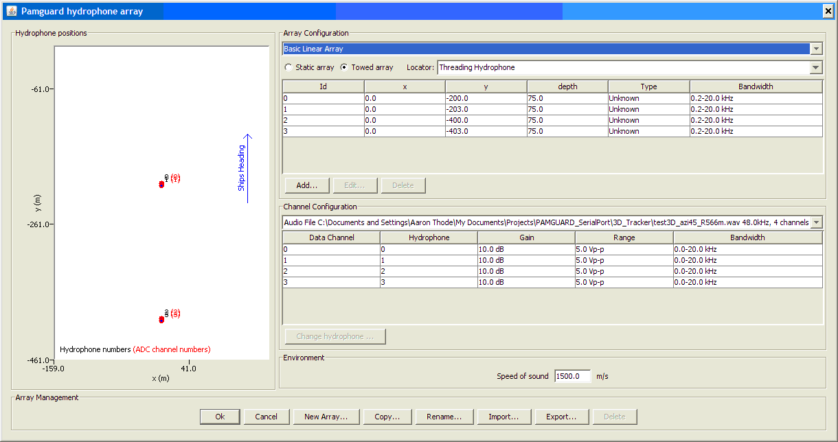
At a minimum the 3D Towed Array module requires an upstream Data acquisition module and a Click Detection module (labeled Sound in and Click Detector in Figure 1). At present the 3D module is configured to only work with the Click Detector, and not any Ishmael detectors. A typical array configuration is illustrated in the following figure, which appears under the Hydrophone display. At present only two pairs of hydrophones (4 phones total) are used in the module.
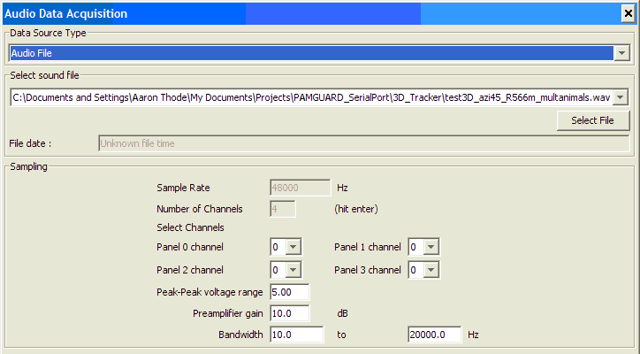
This figure shows the configuration menu for the Audio Data Acquisition module (SoundIn in Figure 1) which should be configured to select a synthetic wav file. The wav file has 4 channels, with the hydrophone closest to the tow vessel being assigned the lowest channel number.
The Click Detection module has many options, but only the following menu needs to be changed from the default, as shown in the following figure.
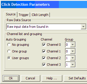
The “Source” tab arrangement shown here assigns the first two channels to Group 0 (thus generating a forward subarray bearing) and the last two channels to Group 1, (generating the rear subarray bearing).
3-D Towed Array Settings
The module assumes that the separation between the two pairs of hydrophones in the array is great enough that an ambiguity may exist as to how to match a particular detection on the rear subarray with candidate detections on the forward subarray. This ambiguity is more likely when multiple acoustically active animals are present. In general, the module also assumes that the array elements are deep enough that surface-reflected paths from pulsive sounds can be cleanly separated in time from the direct paths. The time delay between a direct and surface-reflected path will be defined as an “echo time” for the rest of this discussion. The echo time of a detection, along with the acoustic bearing of the detection, provide a set of features that permit identification of the signal between subarrays.
To match the appropriate signals the program builds a queue of detections for each subarray, and assigns an inter-click interval (ICI) to each detected click. The ICI of a new detection is computed by searching the queue for a detection that shares a similar bearing and “echo time” to the present detection. One the ICI is assigned, the program can build a “linked ICI” list that provides the ICI of the N previous detections that share similar features to the current detection. This ICI list can then be compared to lists on the forward array to locate the corresponding detection on the forward array.
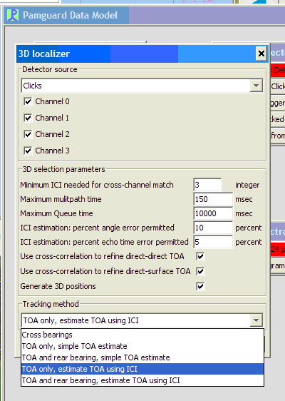
This figure shows the settings menu for the 3-D Towed Array module. The Detector source should be set to ‘Clicks’, and all four channels selected. The selection parameters are as follows:.
Minimum ICI needed: This parameter N defines the number of ICI to incorporate into a list for cross-array comparison. In general the larger the number the less likely a mistake will be made in assigning detections between forward and rear subarrays.
Maximum multipath time: Surface-reflected multipath is flagged by the fact it must arrive only a short time after a direct path. This number sets the maximum “echo time” that will be assigned by the system. Generally, this should be set to twice the hydrophone depth divided by the sound speed.
Maximum Queue Time: Sets the amount of time a particular detection will be retained by the subarray queue, to be available for ICI matching.
ICI estimation: percent angle error: The percent difference between the bearing of a new detection and a candidate detection must be less than this number, in order to use the candidate detection to assign an ICI to the new detection.
ICI estimation: echo time error: Same as above, except the error percentage is computed for the echo time. If an echo time is present, then the bearing and echo time are weighted equally in the decision to link two detections together. If no echo time is present, then only the bearing error is used.
Use cross-correction to refine TOA: The echo times and relative arrival times between subarrays are computed form the detection times provided by a Detection Data Unit. To achieve more precision the raw data between detections can be cross-correlated to increase the precision of the estimate of the relative arrival time. At present only the direct-surface TOA (echo time) feature is enabled.
Generate 3D positions: If not checked, no 2-D or 3-D positions are computed. This is a debug feature to permit the user to set up all other modules before attempting to localize.
Tracking methods
A pull-down menu permits the user to select five different tracking combinations.
Cross bearings: The simplest tracking algorithm simply uses the ICI analysis to generate bearings from the forward and rear subarray, and thus estimate slant range. This slant range is plotted as a horizontal range on the map.
TOA only, simple TOA estimate: If echo times are available on both subarrays, then a track can be computed without having to rely on acoustic bearings. This “TOA only” method is advantageous for situations where the sources are directly ahead or behind the tow vessel, and where the array cable inclination is not measured and cannot be estimated accurately. The “simple TOA estimate” simply means that a detection on the rear subarray is matched to a detection on the forward subarray by simply selecting the detections that have the smallest relative arrival times with respect to each other. For a single animal the “simple TOA estimate” should work more quickly than a full ICI analysis.
TOA and rear bearing, simple TOA estimate: Same as previous, except that the rear subarray bearing, instead of the forward subarray echo time, is used to compute position. Best used for sources off the beam of the vessel and situations where the echo time is not available on the forward subarray. Typical situations where this happens include noise masking from noisy vessels, and shallow hydrophones on the forward subarray.
TOA only: estimate TOA using ICI Same as TOA only option previously discussed, except that ICI patterns are used to match detections on the subarrays. Should be used when multiple animals are present.
TOA and rear bearing, estimate TOA using ICI: Same as TOA and rear bearing option discussed above, except that that ICI patterns are used to match detections on the subarrays. Should be used when multiple animals are present.
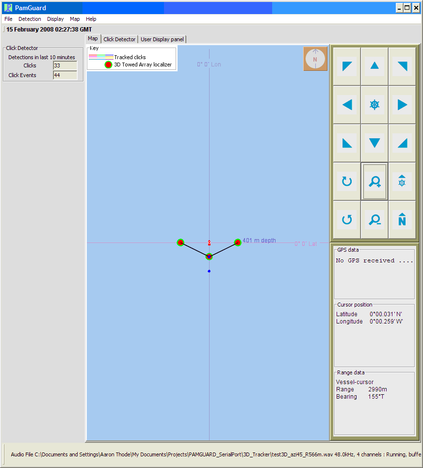
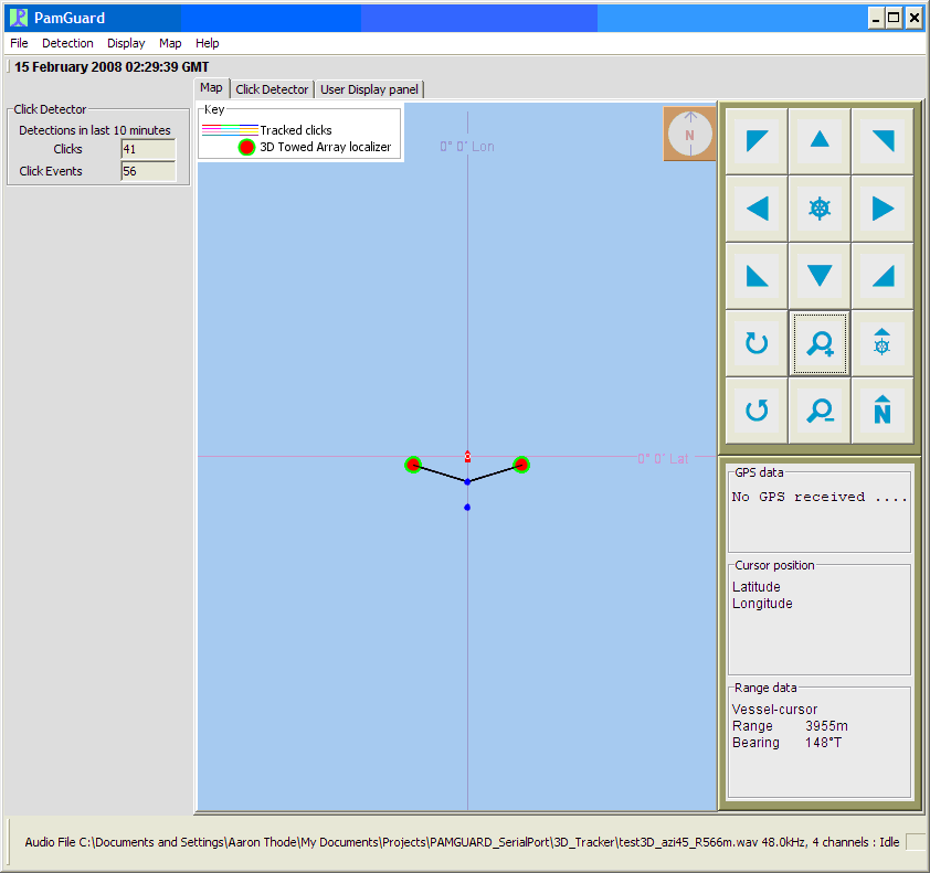
Any 3-D tracking method (TOA option in the Tracking method pull-down menu) will generate a Map image similar to that shown in this figure. The depth of the source is indicated by the size of the circle and by text printed next to the circle.The “Cross bearing” output is demonstrated in the following figure.
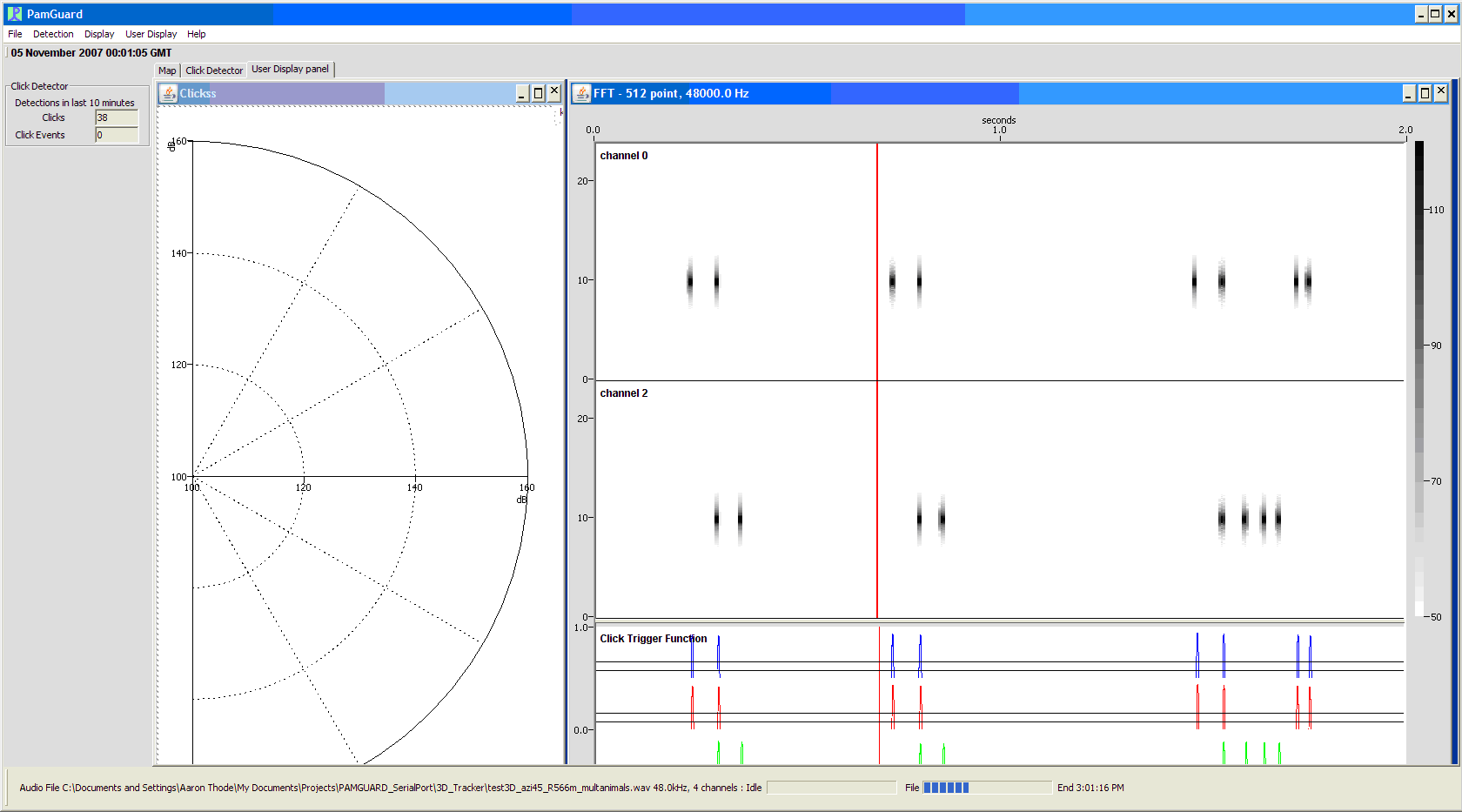
This figure shows Spectrogram and radar plot of simulated 3-D sources on PAMGuard.
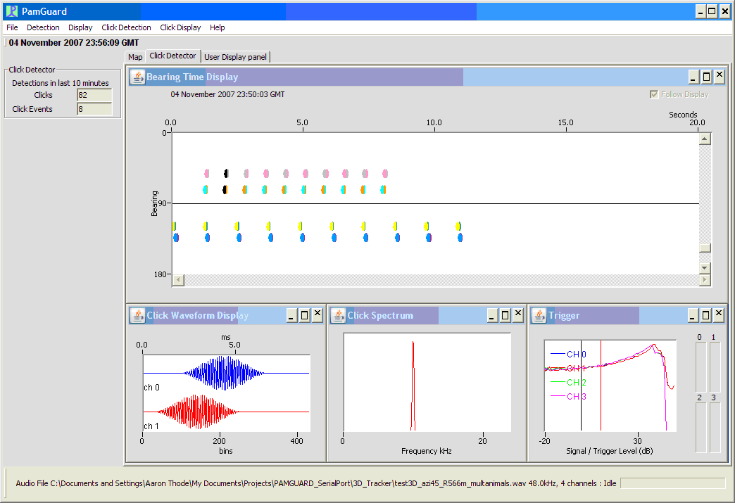
This figure simulated 3D tracking data for multiple animals as it appears in Click Detector view.