Compass Calibration
In addition to providing a magnetic bearing to the source of acoustic detections, the DIFAR module provides a means to �calibrate� the compass of the sonobuoy in order to account for local magnetic anomaly and the magnetic deviation inherent in the compass within the sonobuoy. After �calibration� the DIFAR module will report all bearings referenced to true north. The procedure for �calibrating� the compass is the same as that presented in detail by (Miller 2012, Miller et al. 2013, Miller, Collins, et al. 2014), and basically involves measuring several magnetic bearings to the known positions of the research vessel as it moves away from a sonobuoy after deployment.
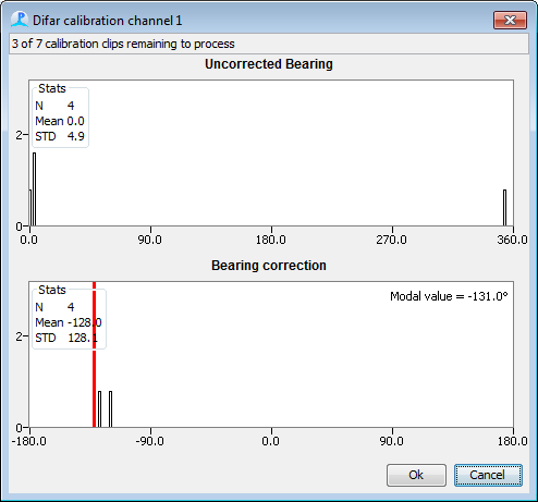
To start a calibration run, press the �Start Calib�� button at the top of the DIFAR queue display. If more than one buoy is deployed, then a drop down menu will appear allowing to select a single buoy. When you start a calibration, a window will appear showing two histograms. The top histogram shows uncorrected (Magnetic) bearings from the buoy, the bottom histogram shows the bearing correction required to line each clip up directly on the vessel.

Naturally there will be some scatter about the true value and there may be some values which are completely incorrect. The operator can right click with the mouse on the lower histogram to select the mean or the modal (most common) value. They can also drag the red line to the required position using the mouse.
Pressing Cancel will abort the calibration run.
When the operator presses OK, a small option dialog will appear asking them to confirm that they wish to update the buoy heading. The updated heading data will then be stored with the PAMGuard Array Manager.
It is possible to simultaneously calibrate more than one buoy at a time.
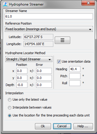
If calibration of a sonobuoy in this manner is not feasible, compass corrections may be entered manually (e.g. using magnetic anomaly from a chart) as the Heading in the Streamer Dialog of the Array Manager. The Use Orientation Data checkbox should be checked.
