Configure Processing
The DIFAR localisation system is configured either from an item in the main Detection menu or by pressing the Settings button at the top of the DIFAR queue panel. Process Settings are laid out across a few different tabs on the dialog. Generally, you will only have to set up the Data and Species tabs and can leave other settings at their default values.
Data and buffers
Processing (Classification/Species)
Calibration
Automation
Data and buffers
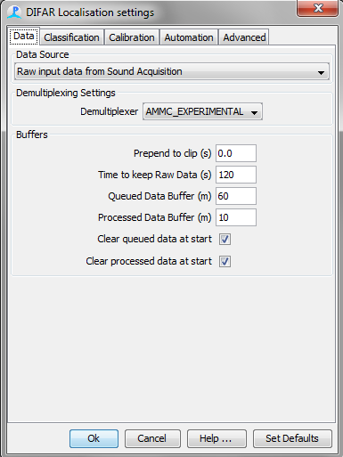
Data Source determines which audio source will be used to when de-multiplexing DIFAR clips. This is generally the sound acquisition module connected to a sound card receiving multiplexed audio data from a VHF radio receiver.
Demultiplexing Settings determines which demultiplexor (demodulator) will be used.
Most DIFAR sonobuoys send data via VHF radio link back to an aircraft of nearby vessel. Consequently, the acoustic data from the three sensors are multiplexed into a single signal prior to transmission. An important part of the processing is therefore the de-multiplexing of the signal back into it�s three separate components, and to achieve this, PAMGuard makes use of a software library developed by Greenridge Sciences Inc. Greeneridge Sciences Demultiplexing Library is not included with PAMGuard and must be purchased separately. Upon purchase, you be supplied with a file GreenridgeDemux32.dll or GreenridgeDemux64.dll, and this should be placed in your Program Files (x86)/PAMGuardBeata/lib folder prior to launching PAMGuard.
An alternative to the Greenridge demultiplexor is the Australian Marine Mammal Centre (AMMC) Experimental Demultiplexor. This freely available, open source demodulator developed at the Australian Antarctic Division is included in PAMGuard within the DIFAR module. The AMMC Experimental Demodulator does not require purchase, and at the time of writing (July 2014) is not subject to export restrictions by the Australian Defence Control Export Agency. However, the AMMC module is considered Beta software and may not be as stable, reliable, or robust as the Greeneridge Demodulator.
The Greenridge demultiplexor is more robust and well tested, but must be purchased separately. The AMMC Expermintal demultiplexer is included by default.
Buffers
Prepend to clip: This is the amount of data (in seconds) added to the start of each DIFAR clip. When using the Greeneridge demodulator, this should be set to approximately 3 s or more to enable the phased lock loop in the DIFAR de-multiplexing module to lock onto the carrier signal. When using the AMMC demodulator, this should be set to 0.
Time to keep Raw Data: The time in seconds that raw data are held in memory. Once data are discarded it is no longer possible to make clips from the data for DIFAR processing. Generally a couple of minutes is adequate. Increasing this too much can cause PAMGuard to run out of memory.
Queued Data Buffer (m): The minimum number of minutes that data are held in the queue prior to processing before being automatically discarded. Additionally, there are also controls on the DIFAR Queue Display to determine how long data are kept in the queue.
Processed Data Buffer (m): The number of minutes that processed data are held prior to being discarded. Additionally, the Map Data Selector can determine how long processed data are kept.
Clear queued data at start: If this is selected, then each time PAMGuard starts, all queued data clips will be discarded.
Clear processed data at start: If this is selected, then each time PAMGuard starts, processed data objects will be discarded, and thus removed from the map.
Classification (Species) Processing
The PAMGuard DIFAR module uses the beamforming algorithms as described by (D�Spain 1994, McDonald 2004) to obtain an estimate of the signal power as a function of tonal frequency and magnetic bearing. We refer to the display of signal power as a function of frequency and bearing as the DIFARGram. For a given detection, the bearing and frequency with the highest power can usually be said to represent the direction of the vocalisation.
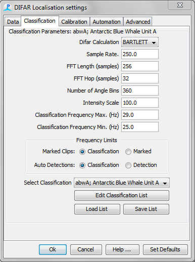
Parameters for creating the DIFARGram are controlled on this tab. The PAMGuard DIFAR module allows for a different DIFARGram parameters to be used for different “Species” (i.e. user-defined classifications) of vocalisations. The Edit Species List button allows the creation of new user-defined species classifications. The Select Species drop-down menu is used to select a species in order to edit itparameters.
DIFARGram parameters
DIFAR calculation allows selection of the beamforming method: either Bartlett or MVDR.
Sample Rate: After de-multiplexing, the data for each clip are decimated to a lower sample rate.
FFT Length: The Fourier Transform length to use during DIFAR processing and display. This must be a power of 2.
FFT Hop: The hop, in samples between successive FFT frames.
No. Angle Bins determines the angular precision when computing the DIFARGram. Generally, 360 bins, for a 1 degree resolution is adequate. Increasing higher than 360 degrees may substantially increase processing times.
Intensity Scale is a numeric factor that controls the color scaling (i.e. contrast) of the DIFARGram. Specifically, a “floor” value is set for the DIFARGram that is equal to the maximum power in the DIFARGram divided by the Intensity Scale. Intensity Scale values between 10 and 10000 provide adequate contrast for most DIFAR data.
Beamforming Frequency Max. and Beamforming Frequency Min. Maximum and Minimum frequencies to use to use when determining the bearings of a DIFAR localisation. For detections that were manually marked on the spectrogram, these values are overridden if the �Marked� button is selected, in which case the frequency limits of the mark made by the operator will be used. For automatic detections, the values will be overridden if the �Detection� button is pressed.
Load/Save List. These buttons can be used to save or load your list of classifications so that these lists can be easily shared and transferred among different settings files.
Calibration
Intensity calibration (sonobuoy frequency response)
Most sonobuoys have a non-flat frequency response i.e. the intensity is shaped as a function of frequency in order to optimise the dynamic range of the FM signals sent across the limited bandwidth of the VHF radio link. The effects of this “pre-whitening” filter must be reversed in order to make calibrated intensity measurements from signals from sonobuoys.
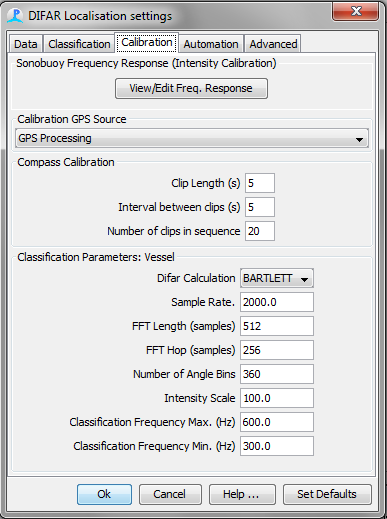
In addtion to the frequency response of the sonobuoy, the frequency response of the VHF receiver must also be taken into account when measuring intensity of signals from sonobuoys that have been received over VHF radio. The View/Edit Frequency Response button can be used to create a single arbitrary FIR filter that will correct for the combined frequency response of the sonobuoy and the VHF receiver. Lastly, to ensure accuracy, make sure that the hydrophone sensitivity in the Array Manager is set to the correct reference sensitivity for each sonobuoy.
Example: A DIFAR 53D sonobuoy is used with a WiNRADiO G39 sonobuoy VHF receiver.
The frequency response of the 53D sonobuoy (figure below) is given relative to the reference pressure (100Hz) and reference intensity (122 dB re 1 uPa RMS; as per Greene et al 2004).
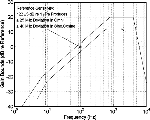
Intensity frequency response of a DIFAR 53D Sonobuoy (adapted from Greene et al 2004)
The hydrophone sensitivity is measured in dB re 1 V/uPa. Therefore the inverse of the reference intensity can be used as the sensitivity of the hydrophone in the Array Manager (Figure Below).
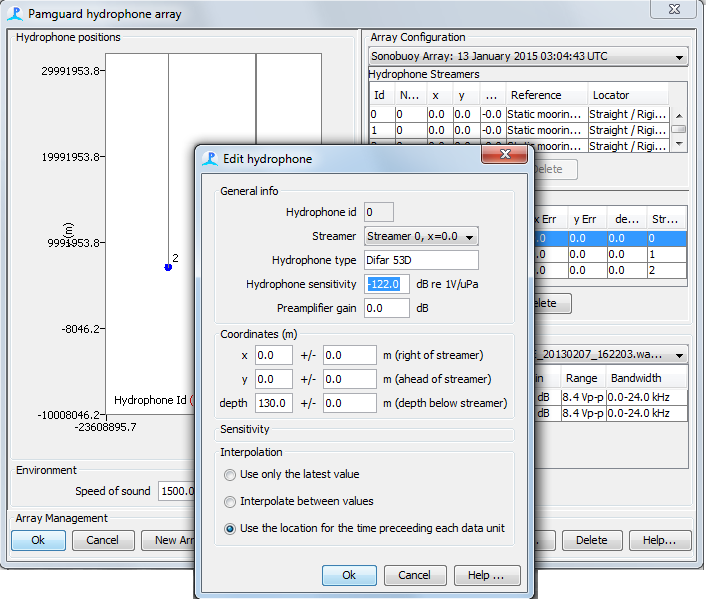
Setting the hydrophone sensitivity in PAMGuard’s Array Manager
At the reference pressure and intensity the sonobuoy will generate a 25 kHz of frequency deviation. The voltage frequency response of the WiNRADiO G39 receiver is then measured at 25 kHz frequency deviation and found to be relatively flat at 1 V (i.e. 0 dB from 10 to 48000 Hz). These two frequency responses are combined and entered into the DIFAR module using the button View/Edit Freq. Response (Figure Below).
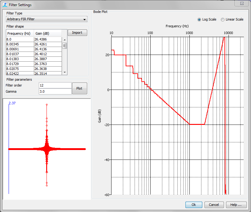
Setting up a filter for obtaining calibrated intensity measurements from sonobuoys
The DIFAR module will now apply this filter to the data from the omnidirectional hydrophone when measuring the intensity (i.e. processing) of an audio clip. The resulting intensity measurements will be accurately referenced to 1 uPa RMS. NB: Specifications from sonobuoy manufacturers typically suggest that intensity is accurate to within �3 dB.
Calibration GPS Source
If multiple GPS modules have been added to PAMGuard (e.g. in viewer mode or mixed-mode for post-processing of data), then this drop-down menu can be used to select the GPS module that contains the position of the calibration sound source.
Compass calibration
In addition to providing a magnetic bearing to the source of acoustic detections, the DIFAR module provides a means to �calibrate� the compass of the sonobuoy in order to account for local magnetic anomaly and the magnetic deviation inherent in the compass within the sonobuoy. After �calibration� the DIFAR module will report all bearings referenced to true north. The procedure for �calibrating� the compass is the same as that presented in detail by (Miller 2012, Miller et al. 2013, Miller, Collins, et al. 2014), and basically involves measuring several magnetic bearings to the known positions of a research vessel as it moves away from a sonobuoy after deployment. See here for details of running the calibration.
Audio clips used for calibration, are treated as a special species and are processed and localised in much the same way as other species. The DIFARGram parameters for calibration clips are controlled using the top portion of this tab. The bottom portion of the tab can be used to set the length and number of clips to include in a calibration run.
Clip length (s): Length of each automatically generated calibration clip.
Interval between clips(s): The number of seconds between automatically generated calibration clips.
Number of clips in sequence: The number of clips to include in the calibration run.
Auto-process vessel clips: When checked, automatically generated calibration clips will be automatically moved from the DIFAR queue to the DIFAR processing module as soon as the previous clip is cleared from the DIFAR processing module.
Automation
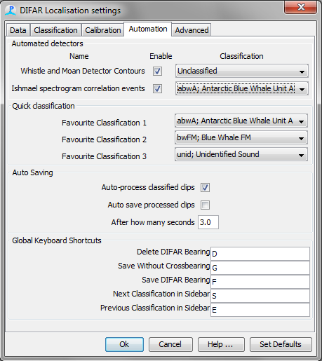
The main purpose of the DIFAR Localisation module is to process signals from directional DIFAR sonobuoys in order to obtain bearings to vocalisations from whales. The detection of whale vocalisations may take place automatically via any PAMGuard detector that can generate clips (e.g Ishmael energy and spectrogram detectors, PAMGuard�s whistle and moan detectors) or can take place via manual selection of calls on the spectrogram. Any number of these automated detectors can be used to present detections to the DIFAR module.
Automated Detectors: This panel lists all of the PAMGuard modules that are capable of generating detections that can be processed and potentially localised with the DIFAR Localisation module. The first column lists the name of the detector, and the checkbox in the second column determines whether or not the detections will be used by the DIFAR Locasitaion module. Be warned though that many detectors produce false alarms at a high rate which may fill the DIFAR queue very rapidly. The final column labelled “Classification” contains a drop-down menu containing all of the “Classifications” known to the DIFAR module. Selection of a classification species will force all of the detections for that detector to be classified and automatically processed accordingly. Automatic detection without automatic processing can be achieved by selecting the “Unclassified” species (i.e. listed first in the “Classification” drop-down menu).
Quick classification: This panel controls which classifications, if any, will be prominently visible next to each detection in the DIFAR Queue. There can be up to three �Favourite� species which will appear as buttons next to each clip in the DIFAR queue. NB: Species that are not “Favourites” will be available via a drop-down menu next to each clip.
Auto Saving (and auto-processing)
Auto-process classified clips: When this box is checked, clips that have a classification will be automatically processed (i.e. DIFARGrams will be created and displayed). If not checked, then the user must click on the Process button next to each clip in the DIFAR queue to process each clip.
Auto save processed clips: If you select to Auto save processed data, then once a DIFAR clip has been processed it will automatically be saved after the set delay time using the maximum DIFAR angle and automatically crossing bearings to other detections if more than one buoy is in operation.
Global Keyboard Shortcuts:
Keyboard shortcuts can be assigned to any or all of the five actions listed under this panel. If any of these keys are pressed in any PAMGuard window (including, but not limited to windows created by the DIFAR module) their corresponding actions will be carried out if possible. Three of these actions, Save, Save without Crossbearing, and Delete have corresponding buttons on the DIFARGram. The remaining two actions will change the selected classification in the DIFAR Selection sidebar.
Advanced
Use DifarGram summary line: When checked the angle with the maximum value of the summary line in the DifarGram will be automatically selected for newly processed bearings. When unchecked, the angle and frequency with that contain the maximum value of the DIFARGram will be selected for newly processed bearings.