Patch Panel
Patch Panels can be used to re-order channels, duplicate channels and mix data from multiple channels
A patch panel can be inserted anywhere in the PAMGuard data model where there are raw audio data.
Creating a Patch Panel
From the File>Add modules>Sound Processing menu, or from the pop-up menu on the data model display select “Patch Panel”. Enter a name for the new Patch Panel module (or keep the default “Patch Panel”) and press Ok.
Configure the Patch Panel
The Patch Panel module requires a source of raw data before it can operate. This may come directly from a Sound Acquisition module (e.g. a sound card or a National Instruments board) or from processed data such as the output from a filter, a decimator, etc.
To configure the Patch Panel, go to the Detection>“your patch panel name …”> menu

Select the data source at the top of the dialog.
Patch Panel Settings
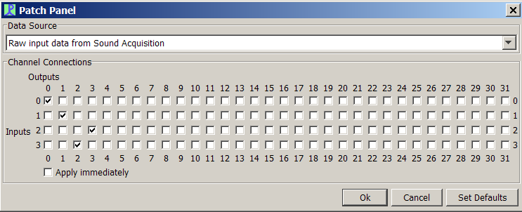
Inputs to the patch panel are shown down the left hand side of the matrix. The number of inputs will be equal to the number of channels in the data source.
Outputs are shown along the top. There will always be 32 output channels available.
Check the boxes to link input channels to output channels.
In the example, the patch panel has been used to reverse the order of channels 2 and 3.
Apply Immediately
If the “Apply Immediately” box is checked, then changes to the patch panel matrix become effective immediately.