Configuration
From the File>Add modules>Utilities menu, or from the pop-up menu on the data model display select ‘Hydrophone Depth Readout’. Enter a name for the new module and press Ok.
The depth readout module is not dependent on any other modules and will automatically find and exchange information with the Hydrophone Array Manager. Go to Detection>Hydrophone Depth Readout Settings… for configuration.

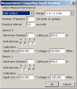
Select Measurement Device
Select the data acquisition card you wish to use. Depending on the card type, it may be necessary to first configure the card using software provided by the card manufacturer. For Measurement Computing cards, you will need to run their ‘instacal’ configuration utility. You should also refer to your device manual.
Select the maximum voltage range of the device. Generally, this should be as small as possible, since this will improve resolution. Obviously, the range has to be greater than the maximum values you are expecting from your sensor.
Set the number of sensors and the interval between readouts. After changing the number of sensors, hit ‘Enter’ and the number of panels in the lower part of the dialog will change accordingly.
Sensor Configuration
For each sensor, set the data acquisition cards hardware channel, the position on the cable and the hydrophone channels data from that sensor should be applied to.
If more than one sensor is set to apply data to the same hydrophone, then the actual hydrophone depth is calculated using linear interpolation based on the relative positions of the hydrophones and the depth sensors. This feature would be useful in longer arrays which may not be towing horizontally and contain more than one depth sensor.
Calibration
The depth is calculated from the measured voltage using a simple linear model of the form
Depth = A * Voltage + B,
where A and B are constants.